The KE-jetronic system also belongs to the group of CIS injection system which stands for continuous injection system . This means that the fuel is continuously injected into the inlet collector. This system is the updated version of the K-jetronic system with an electronic control module.

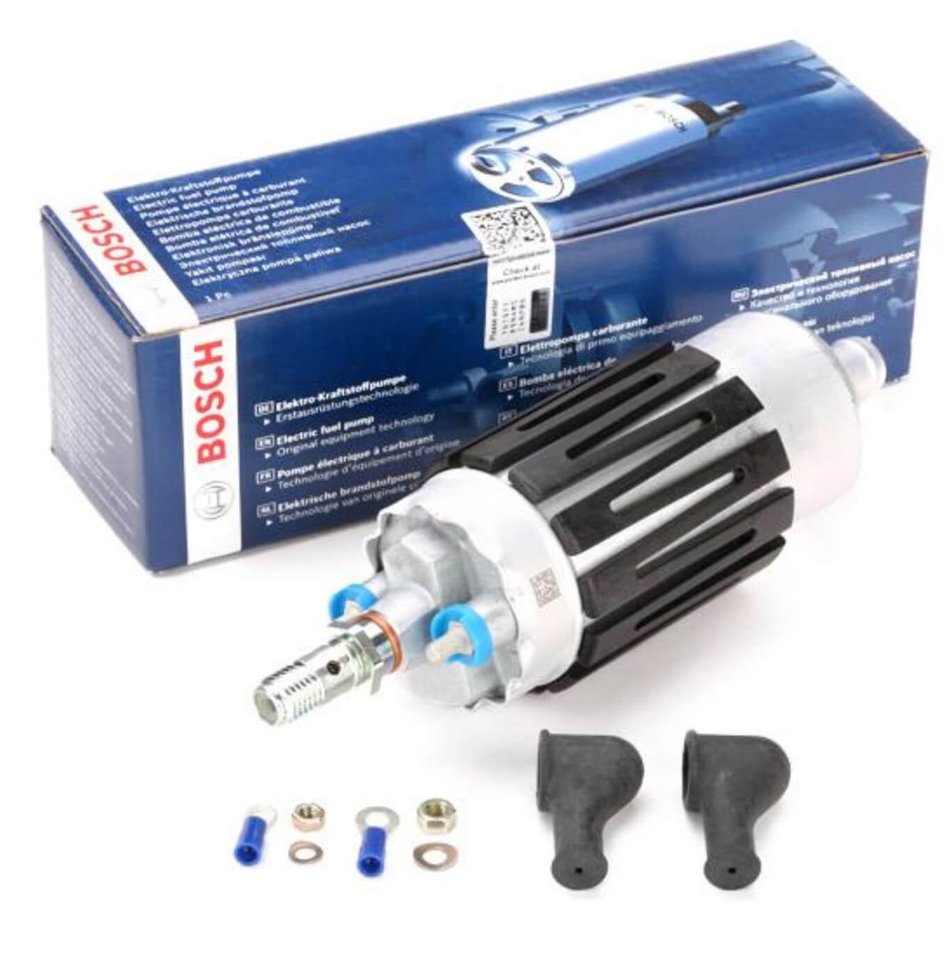
2 Fuel pump
The fuel pump is used to supply the system with the necessary fuel pressure. Just after the fuel pump, a non-return valve is installed which is needed to keep the system pressurised after the engine has been switched off.
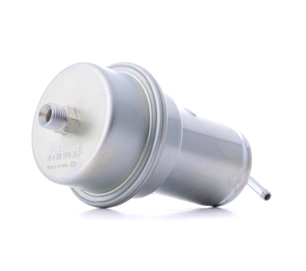
3 Fuel accumulator
The fuel accumulator has 2 functions:
- After the engine has been switched off, the fuel system is kept under pressure by this accumulator to promote a warm start.
- The accumulator dampens out the fuel pulses generated by the fuel pump.
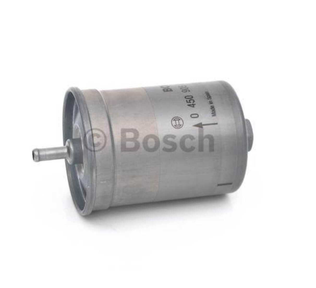
4 Fuel filter
The purpose of the fuel filter is to filter the fuel so that it does not pollute the system.
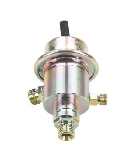
5 Fuel pressure regulator
The pressure regulator regulates the petrol pressure, in contrast to the K-Jetronic system, this component is not mounted in the fuel distributor.
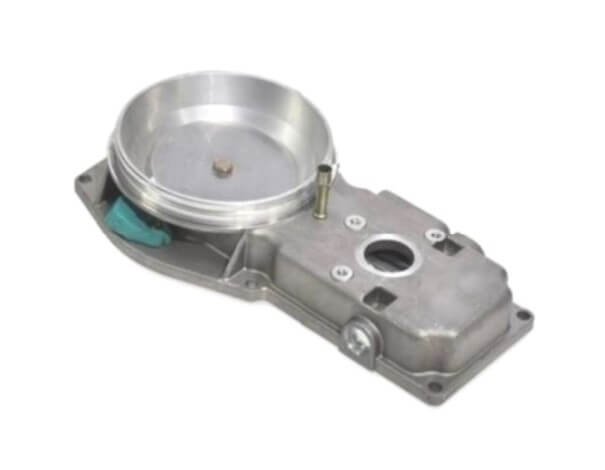
6 Air flow meter
The air flow meter measures the amount of air drawn in by the engine. Based on this measurement, the fuel mixture is mechanically adjusted.
7 Fuel distributor
The fuel distributor, has the function of supplying the different cylinders with exactly the same amount of fuel. On the KE-jetronic system there is an electro-hydraulic pressure regulator (17).
This component is overhaulable.

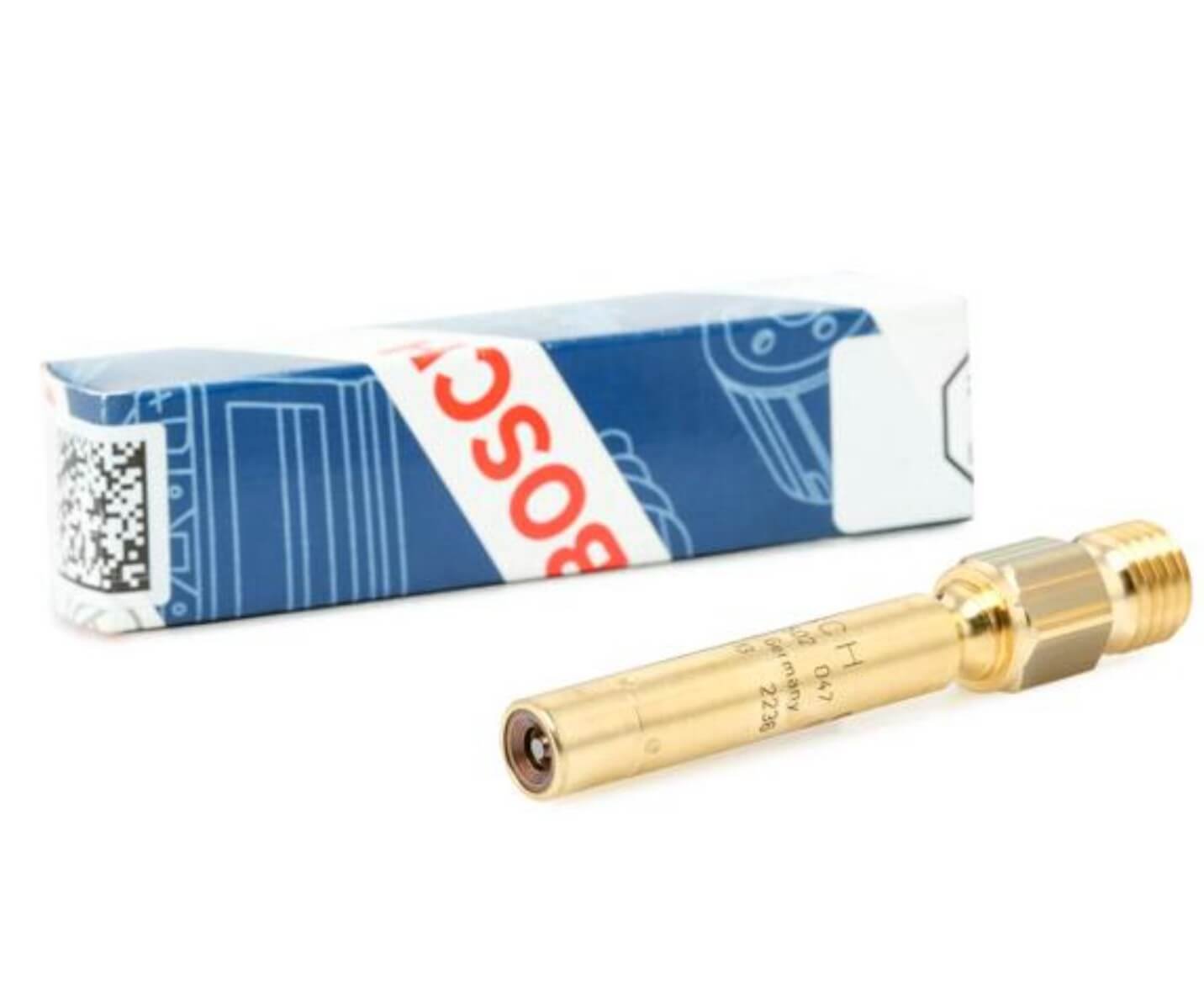
8 Injector
The injector provides a nicely atomised fuel so that the fuel-air mixture is as homogeneous as possible.
10 Cold start injector
The cold start injector, adds extra fuel at very low ambient temperatures.
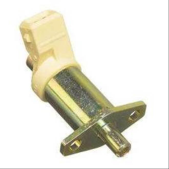

11/15 Thermo time switch
The thermo time switch is used first of all to control the injection time of the cold start injector (8). The engine temperature sensor is used as input for the ECU.
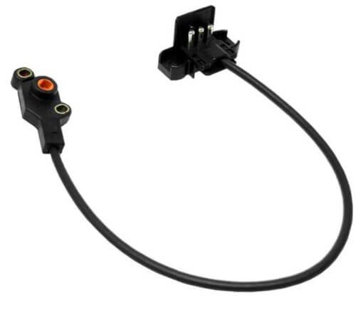
13 Throttle valve switch
The throttle valve switch gives an input signal to the ECU.
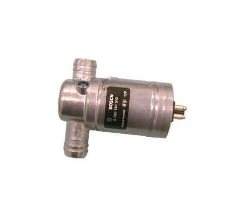
14 Air slide valve
The purpose of the air slide is to supply more air when the engine is cold. This air slide can be operated electrically or it is directly connected to the coolant. In some configurations, the valve also controls the idle speed.
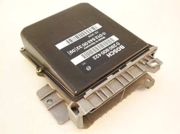
16 Control unit
The control unit (ECU) processes the various inputs in order to provide the desired signal to the different components and thus obtain the optimum fuel mixture for each circumstance.
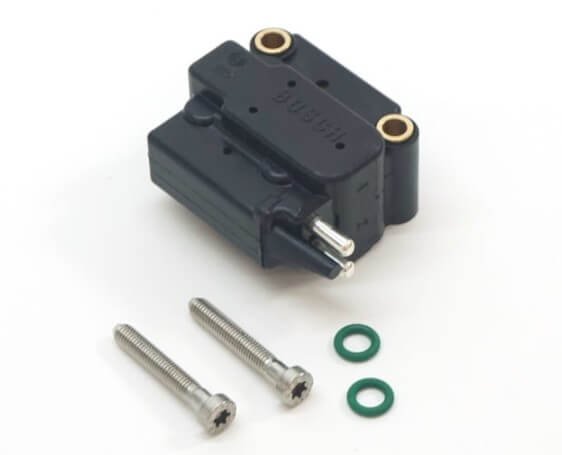
17 Electro-hydraulic pressure regulator
The electro-hydraulic pressure regulator controls the pressure in the lower chambers of the fuel distributor (7) according to the signal from the electronic control unit (16).
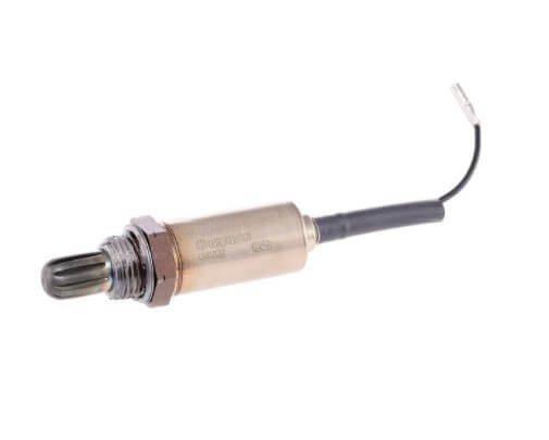
18 Lambda-sonde
The lambda-sensor generates a signal that the control unit uses to adjust the fuel mixture. The lambda sensor only generates a signal if the component has a sufficiently high temperature.
