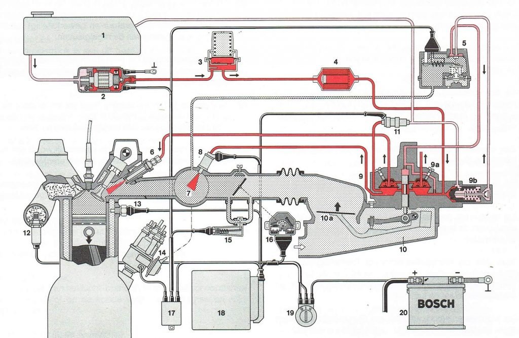
The Bosch K-jetronic system is made up of different components, which are discussed below and their functions. Only the components related to the system are shown below. The same categories can be found in the Shop area where the available parts are displayed.
The K-jetronic system belongs to the group of CIS injection system which stands for continuous injection system. This means that the fuel is continuously injected into the inlet manifold. The system is completely mechanical. From the end of 1979, this system was modified by adding a lambda control system (KA-jetronic). This system is shown in the figure below, the components 11, 12, 16 and 18 are specific to this lambda control system and are therefore not present in a mechanical K-jetronic system.
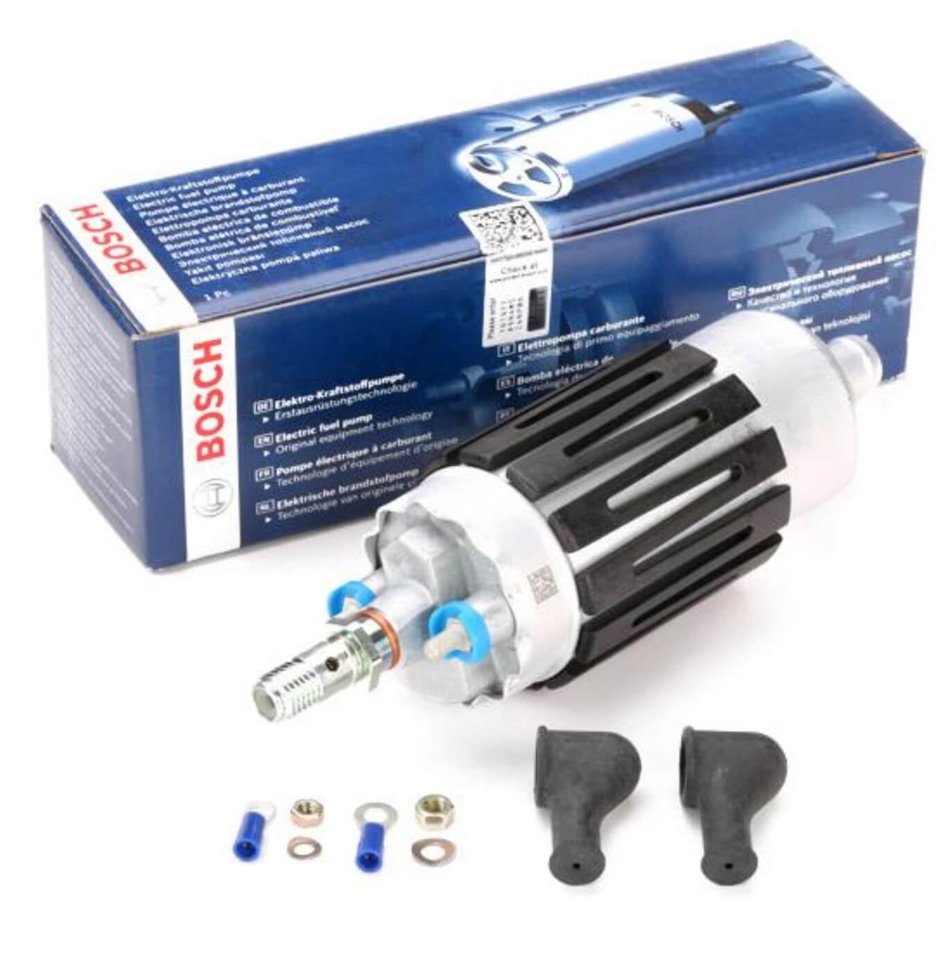
2 Fuel pump
The fuel pump is used to supply the system with the necessary fuel pressure. Just after the fuel pump, a non-return valve is installed which is needed to keep the system pressurised after the engine has been switched off.
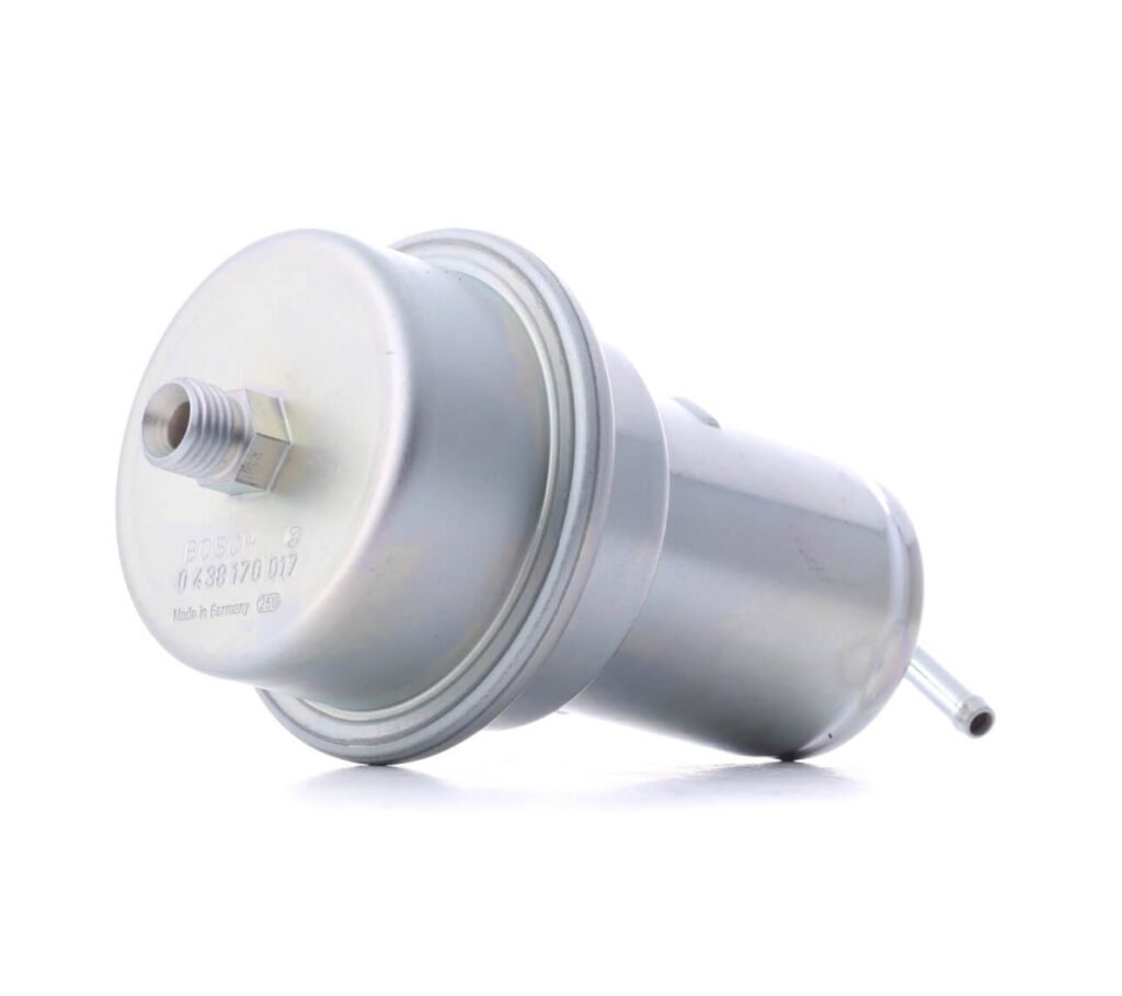
The fuel accumulator has 2 functions: - After the engine has been switched off, the fuel system is kept under pressure by this accumulator to promote a warm start. - The accumulator dampens out the fuel pulses generated by the fuel pump.
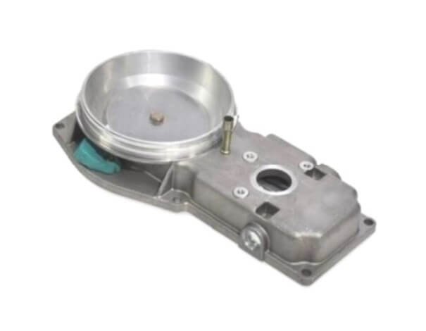
The purpose of the warm up regulator is to enrich the fuel mixture during a cold start. When the engine warms up, the mixture is depleted to the correct ratio.
This component can be overhauled, the necessary components can be found in the shop.
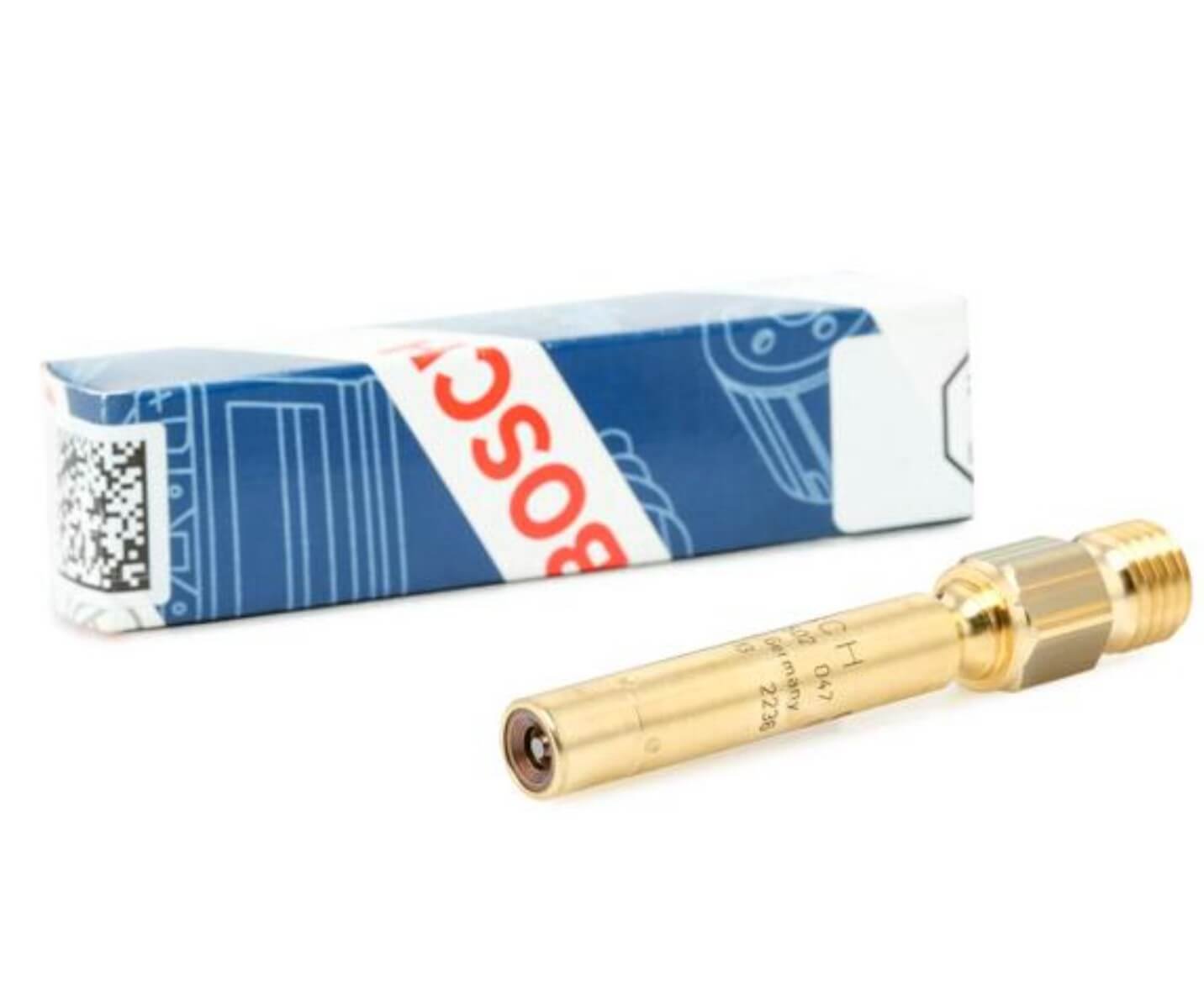
The cold start injector, adds extra fuel at very low ambient temperatures.
9 Fuel distributor
The fuel distributor, has the function of supplying the different cylinders with exactly the same amount of fuel. Some versions have a fuel pressure regulator built in internally. This part can be overhauled.
The air flow meter measures the amount of air drawn in by the engine. Based on this measurement, the fuel mixture is mechanically adjusted.
11 Timing valve
This control valve is used with KA-jetronic systems. Here the fuel mixture is regulated by means of a lambda-probe control system. The control valve changes the pressure between the upper and lower chamber of the fuel distributor, thus changing the fuel mixture.
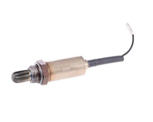
12 Lambda-sensor
The lambda-sensor (only on KA-jetronic) generates a signal that the control unit uses to adjust the fuel mixture. The lambda sensor only generates a signal if the component has a sufficiently high temperature.
13 Thermo time switch
The thermo time switch is used first of all to control the injection time of the cold start injector (8). If a lambda control system is fitted, this sensor is also used as an input for the control device (18).
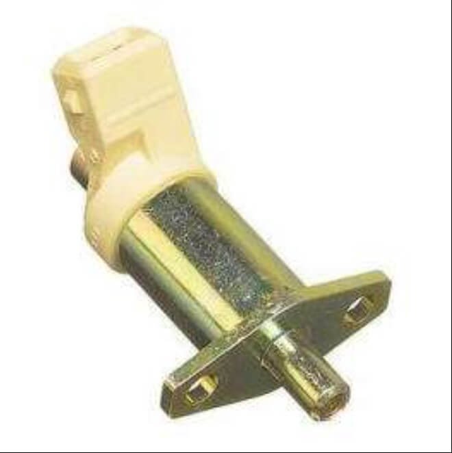
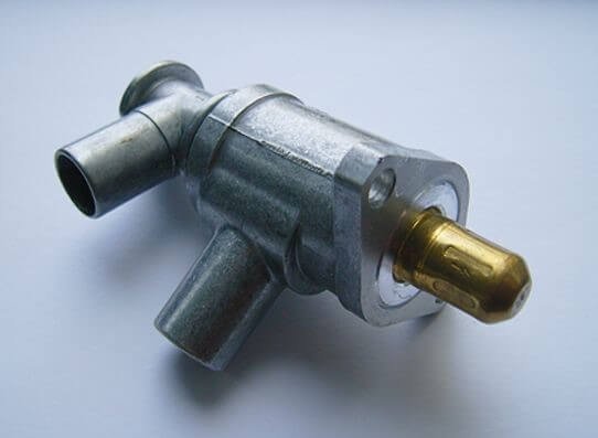
15 Auxiliary air valve
The purpose of the auciliary air valve is to supply more air when the engine is cold. This air slide can be operated electrically or it is directly connected to the coolant system.
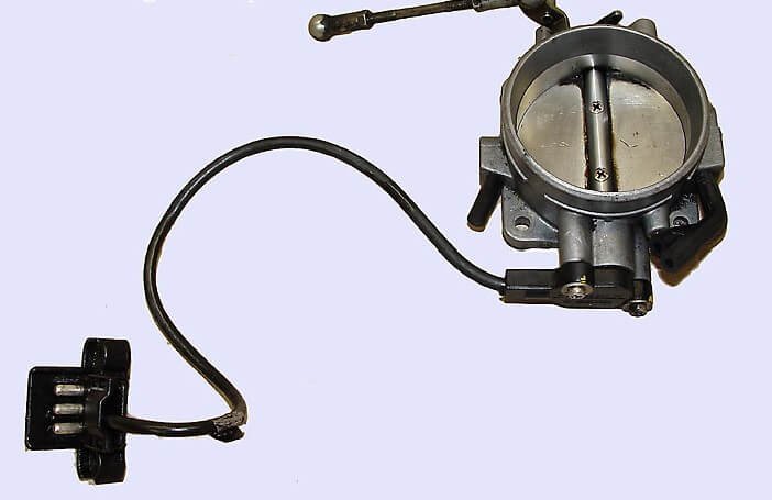
16 Throttle valve switch
The throttle switch is only used in systems with a lambda control system. This switch is present so that the control unit knows the gas position.
18 Control unit
The control unit (ECU) processes the various inputs to provide the desired signal to the control valve (11), thus optimising the fuel mixture.
Shopping Basket
We gebruiken cookies op onze website om u de beste ervaring te geven door uw voorkeuren te herkennen. Door op 'alles accepteren' te klikken, accepteert u om alle cookies te gebruiken. Indien u dit niet wenst, kan u dit aanpassen in de 'cookie settings'.
This website uses cookies to improve your experience while you navigate through the website. Out of these, the cookies that are categorized as necessary are stored on your browser as they are essential for the working of basic functionalities of the website. We also use third-party cookies that help us analyze and understand how you use this website. These cookies will be stored in your browser only with your consent. You also have the option to opt-out of these cookies. But opting out of some of these cookies may affect your browsing experience.
Necessary cookies are absolutely essential for the website to function properly. These cookies ensure basic functionalities and security features of the website, anonymously.
Cookie
Duur
Omschrijving
cookielawinfo-checkbox-analytics
11 months
This cookie is set by GDPR Cookie Consent plugin. The cookie is used to store the user consent for the cookies in the category "Analytics".
cookielawinfo-checkbox-functional
11 months
The cookie is set by GDPR cookie consent to record the user consent for the cookies in the category "Functional".
cookielawinfo-checkbox-necessary
11 months
This cookie is set by GDPR Cookie Consent plugin. The cookies is used to store the user consent for the cookies in the category "Necessary".
cookielawinfo-checkbox-others
11 months
This cookie is set by GDPR Cookie Consent plugin. The cookie is used to store the user consent for the cookies in the category "Other.
cookielawinfo-checkbox-performance
11 months
This cookie is set by GDPR Cookie Consent plugin. The cookie is used to store the user consent for the cookies in the category "Performance".
viewed_cookie_policy
11 months
The cookie is set by the GDPR Cookie Consent plugin and is used to store whether or not user has consented to the use of cookies. It does not store any personal data.
Functional cookies help to perform certain functionalities like sharing the content of the website on social media platforms, collect feedbacks, and other third-party features.
Performance cookies are used to understand and analyze the key performance indexes of the website which helps in delivering a better user experience for the visitors.
Analytical cookies are used to understand how visitors interact with the website. These cookies help provide information on metrics the number of visitors, bounce rate, traffic source, etc.
Advertisement cookies are used to provide visitors with relevant ads and marketing campaigns. These cookies track visitors across websites and collect information to provide customized ads.